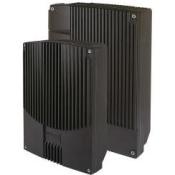
- GSM Series: UNSG3 (GSM 850MHz) | UNSG6 (GSM 900MHz) | UNSG8 (GSM 1800MHz) | UNSG9 (GSM 1900MHz)
- CDMA Series: UNSC1 (CDMA 450MHz) | UNSC3 (CDMA 800MHz) | UNSC9 (CDMA 1900MHz)
- WCDMA: UNSW5 (WCDMA 2100MHz) | UNSW3 (WCDMA 850MHz) | UNSW9 (WCDMA 1900MHz)
- LTE: UNSL2 (LTE 700MHz) | UNSL8 (LTE 1800) | UNSL9 (LTE 1900MHz) | UNSL7 (LTE 2600MHz)
- IDEN: UNSI3 (IDEN 800MHZ)
Description
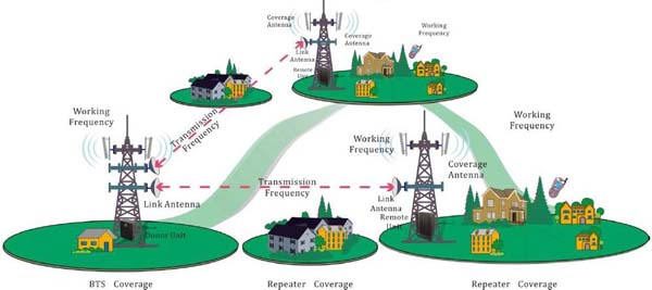
 Frequency Shift Cellular Repeater (FSR) system is designed to solve problems of weak mobile cellular signal, which can expand more coverage than RF repeaters and reduce investment for the areas where fiber optic or dedicated cable is not allowed. The Frequency Shifting Repeaters system (FSR) consists of two parts: Donor Unit and Remote Unit. The Donor Unit receives the BTS signal via open air radio frequency (RF) transmission or direct couple closed to BTS, then coverts it from the working channel to transmission channel that is out of working frequency band, and transmits the amplified signal to the Remote Unit that will reconvert the signal to the working channel and provide signal to the areas where network coverage is inadequate.
As per the method of receiving BTS signal by the Donor Unit, two types of FSR are available:
- Cable-Access FSR: to receive BTS signal via a direct coupler closed to the BTS (Recommended);
- Wireless-Access FSR: the receive BTS signal via a Donor Antenna (applicable when no line of sight can be viewed between the Donor Unit and Remote Unit as the Donor Unit is installed on the BTS tower).
- In-band FSR: the link frequency is within the working band of BTS;
- Out-of-Band FSR: the link frequency is out of the working band of BTS.
Features
- Aluminum-alloy casing with IP65 protection
- Compact design, cool system without fan
- Best solution to eliminate mutual interference due to sharing the same frequency
- ALC and AGC to ensure stable operation
- Easy to install on wall or pole
- Highly selective channel selector can process 1 or 2 or 4 or 6 or 8 channels simultaneously
- Max transmission distance between Donor Unit and Remote Unit is 20KM
- Filter with highly selectivity and low insertion loss eliminates interference between uplink and downlink
- Built-in wireless modem (Option) for remote monitoring by SMS
- Details repeater parameters and status can be monitored by software
- High gain linear power amplifier technique with reliable performance
- Eliminate isolation requirement in antenna installation
- Easy to choose installation site
Application
- Outdoor: Airports, Tourism Regions, Golf Courses, Tunnels, Factories, Mining Districts, Villages, ……
- Indoor: Hotels, Exhibition Centers, Basements, Shopping Malls, Offices, Packing Lots, ……
The FSR is mainly applicable to such case:
- The area to be covered is far away from the BTS and has no fiber optic connection;
- The distance between the BTS and the area to be covered is 20KM around.

Direct Couple Type Frequency Shift Cellular Repeater

Wireless Couple Type Frequency Shift Cellular Repeater

Multi-link Type Frequency Shift Cellular Repeater
Specification
| Donor Unit | Remote Unit | ||
|---|---|---|---|
| Working Frequency (customizable) | Uplink | 452.5~457.5MHz / 806~824MHz/824~849MHz / 890~915MHz / 1710~1785MHz / 1895~1910MHz | |
| Downlink | 462.5~467.5MHz / 851~869MHz/869~894MHz / 935~960MHz / 1805~1880MHz / 1975~1990MHz | ||
| Link Frequency | Customizable | ||
| Transmission Distance | ≤ 20km | ||
| No. of Channels (for channel shift) | 1 / 2 | ||
| Frequency Error | ≤ 0.05ppm | ||
| Output Power (customizable) | Uplink | Cable-Access: ≥ 0dBm Wireless-Access: ≥ 30dBm |
≥ 33dBm |
| Downlink | 30~40dBm (1W~10W) | 37~43dBm (5W~20W) | |
| Downlink Input Level | Cable-Access: ≥ -10dBm / Wireless-Access: ≥ -70dBm | ||
| Gain | Cable-Access: ≥ 45dB Wireless-Access: ≥ 85dB |
≥ 90dB | |
| Gain Adjustment Range | 1~31dB @ step of 1dB | ||
| Voltage Standing Wave Ratio (VSWR) | < 1.3 | ||
| Noise Figure | < 5dB (only for uplink) | ||
| Spurious Emission | Within working band | ≤ -15dBm/30kHz | |
| Out of working band (Δf > 2.5MHz) |
9kHz~1GHz: ≤ -36dBm/100kHz 1GHz~12.75GHz: ≤ -30dBm/30kHz |
||
| In-Band Intermodulation Attenuation | ≤ -40dBc/30kHz | ||
| Out-of-Band Suppression | Per band | Δf > 2.5MHz: < -40dBc (downlink); Δf > 10MHz: < -60dBc (uplink) | |
| Per channel | Δf > 1.98MHz: < -44dBc (downlink); Δf > 1.98MHz: < -38dBc (uplink) | ||
| In-Band Ripple | ≤ 3dB p-p | ||
| System Delay | ≤ 10μSec | ||
| I/O Impedance | 50Ω | ||
| RF Connector | N-Type (Female) | ||
| Temperature Range | Operation: -25°C ~ +55°C / Storage: -30°C ~ +60°C | ||
| Relative Humidity Range | ≤ 95% (non condensing) | ||
| Power Supply (customizable) | DC +24V / DC -48V / AC 220V±15%, 50Hz / AC 110V±15%, 50Hz | ||
| Backup Power Supply (optional) | 4 hours | ||
| Casing Level | IP65 | ||
| Dimensions | 630mm X 400mm X 230mm | Output power @37~40dBm: 570mm X 325mm X 215mm Output power @40~43dBm: 630mm X 400mm X 230mm |
|
| Weight | 33kg | Output power @37~40dBm: 27kg Output power @40~43dBm: 35kg |
|
| Remote Monitoring/Control via NMS | Supported | ||
| ALC (Automatic Level Control) | Supported | ||

 Mobile Signal Booster