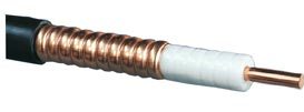
 1/2" Feeder Cable is a type of RF coaxial cable which is used in many applications where it is necessary to transfer radio frequency energy from one point to another such as In-building distribution system and various wireless communication system. It incorporates high foaming polyethylene insulation technology to minimize signal loss and have excellent electric features such as low damping and reflection coefficient.
This cable carries current in both the inner and the outer conductors. These current are equal and opposite and as a result all the fields are confined within the cable and it neither radiates nor picks up signals. This means that the cable operates by propagating an electromagnetic wave inside the cable. As there are no fields outside the coax cable it is not affected by nearby objects. Accordingly it is ideal for applications where the RF cable has to be routed through or around buildings or close to many other objects.
Specification
Specifications - Construction
| Inner Conductor | Copper-clad aluminum wire | Φ 4.8 mm |
| Dielectric | Cellular polyethylene | Φ 12.1 mm |
| Outer Conductor | Corrugated copper tube | Φ 13.9 mm |
| Jacketing | Black, halogen-free fire-retardant thermoplastic / Black, halogen-free polyethylene (optional) |
Φ 16.0 mm |
| Marking | Trademark, cable type, manufacture week, year, batch number and meter mark | -- |
Specifications - Electrical Characteristics at +20°C
| Characteristic Impedance | 50 ± 1 Ω |
| Return Loss | 24 dB for 100 m cable with connectors |
| Attenuation | See table below |
| Velocity Factor | 0.88 |
| Capacitance | 76 pF/m |
| Maximum Frequency | 9800 MHz |
| Max Power Rating | See table below |
| Peak RF Voltage Rating | 1.80 kV |
| Peak Power Rating | 31.8 kW |
| DC Resistance | Inner conductor: 1.44 Ω/km, Outer conductor: 2.24 Ω/km |
| Frequency (MHz) | Attenuation (dB/100m) | Power Rating (kW) | Frequency (MHz) | Attenuation (dB/100m) | Power Rating (kW) | |
|---|---|---|---|---|---|---|
| 10 | 0.665 | 12 | 900 | 6.85 | 1.2 | |
| 30 | 1.16 | 6.9 | 950 | 7.06 | 1.1 | |
| 50 | 1.51 | 5.3 | 960 | 7.10 | 1.1 | |
| 88 | 2.01 | 4.0 | 1000 | 7.26 | 1.1 | |
| 100 | 2.15 | 3.7 | 1200 | 8.02 | 0.98 | |
| 108 | 2.24 | 3.6 | 1400 | 8.74 | 0.90 | |
| 174 | 2.86 | 2.8 | 1600 | 9.41 | 0.83 | |
| 200 | 3.08 | 2.6 | 1800 | 10.0 | 0.78 | |
| 300 | 3.81 | 2.1 | 1900 | 10.4 | 0.76 | |
| 400 | 4.43 | 1.8 | 2000 | 10.7 | 0.74 | |
| 450 | 4.72 | 1.7 | 2200 | 11.3 | 0.70 | |
| 500 | 4.99 | 1.6 | 2400 | 11.8 | 0.66 | |
| 512 | 5.06 | 1.6 | 2600 | 12.4 | 0.63 | |
| 600 | 5.50 | 1.4 | 2800 | 12.9 | 0.61 | |
| 700 | 5.98 | 1.3 | 3000 | 13.4 | 0.58 | |
| 800 | 6.43 | 1.2 | 3400 | 14.4 | 0.54 | |
| 850 | 6.64 | 1.2 | 6000 | 20.2 | 0.39 | |
| 890 | 6.81 | 1.2 | 8800 | 25.5 | 0.31 |
* Attenuation values are typical at ambient temperature +20°C. Power rating ambient temperature +40°C, inner conductor +100°C.
Specifications - Mechanical Characteristics
| Weight | 0.23 kg/m |
| Maximum Pulling Force | 2550 N |
| Minimum Bending Radius | Single Bending: 70mm, Repeated Bending: 120 mm |
| Operating Temperature Range | -55 ~ +80 °C |
| Crush Resistance | 2.0 kg/mm |
| Bending Moment | 3.8 Nm |
| Recommended Clamp Distance | 1.0 m |

 Mobile Signal Booster